Monday, 27 October 2008

Final Steps

The next step was to prepare the face for texturing. To do this, I had to apply a checkered map to my model. In this way, I could find any ares where pixels would be stretched, and fix these areas.

To do so, I used the UVM Unwrap function, and altered the vertices to give a more flowing, less stretched look to the texture. It was now ready for the next stage.


Next, I had to use the UMV Unwrap tool to create a render of the mask's shape. Since it was only half of the mask, I had to apply the UMV Wrap to the face, above the Symmetry modifier to affect the whole thing. I then mirrored the other half, and welded the two halves together along the seam to create this render of the mask's shape.


Next, in Photoshop, I used this framework to cut and paste sections of the original photo onto the image of the mesh, to make sure that the final result would fit onto the mask in 3D.


I slowly built up the image in segments, testing it occasionally to see how it was displaying in the 3D render.


Finally, once this was almost complete, I used the smudge and clone tools in Photoshop to clear up any gaps or seams in the image, and make sure it matched the shape of the mask closely. I did not manage to texture the back of the face, as without the side it was very difficult to match up the images.


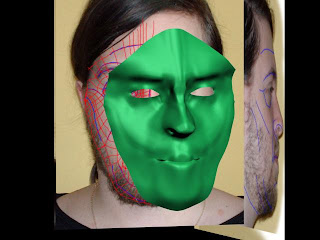
Once that was done, I applied the final image to the face, to give it this more realistic texture, and achieve this final result:


I was quite pleased with the result, as I found this task very challenging. The project was probably one of the hardest things I have had to do in computing, even outside of 3D Max. However, I feel that I have learned quite a lot of new tricks, which I will be putting into later 3D projects.

Friday, 24 October 2008

Depth and Eyeballs

The next step was to start expanding to the top of the skull and the back of the head.

To do so, I created a sphere, and cut out the top and back section, which was then welded onto the left half of the face (not the whole face, because the skull would be mirrored in the same was as the face, once the two were connected.)


Onec this was done, the next stage was to build up the side of the face. However, after much work I was not happy with the result. I did not think it had been connected correctly, so after much consideration I decided that due to time constraints I would stick with the side-less model of the head and move on to texturing to get the most out of the project, rather than spending lots of time trying to fix this problem. I would have kept the sides if they were suitable, but I felt that they would cause problems in the future as the textures would be stretched incorrectly.


Next, I added some eyes to the model. To do so, I found an image of an eye that I could modify. I then used photoshop to turn the round image into a square one that could be used for a spherical map:


This was then mapped onto two spheres that were placed just behind the eyelids on the 3d Model.


Tuesday, 21 October 2008

Week 4 - Adding Detail

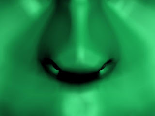
The next step was to add detail to the nostrils, where up until this point there was just a hole. To add in the detail, I selected all of the edges around the hole, then used the scale tool to clone the outer quads and create a ring effect inside the hole.


This is the effect that it produced when rendered:

To avoid the apparent "holes" and add a bit more realism, I then repeated the cloning method around the inner ring, and pulled these quads back to give the inside of the nostrils a bit of depth.

The next stage was to create lips. This part was very difficult, as the tutorial more or less skips this section and left me to my own devices. So, using a similar method to the nostril I cloned the top half of the inner upper lip and curved it round by repeating the cloning method. I then did the same on the lower lip, and tried to mold the vertices into a realistic shape.


Lastly I used the same cloning method to add a ridge to the eyelids, cloning the inner quads and pulling them into the face to create a lip rather than a flat corner where the hole meets the lids.


Thursday, 16 October 2008

Turning 2D to 3D

This was the most time consuming and confusing part of this project so far. Looking at my 2D polygon I had made, it appeared flat like paper from the side. Now, I had to take every individual vertex in the image, and pull it along the X axis to the point which matched the topology of the side view of the face. In doing so, the vertices were slowly placed in a 3D formation, and began to build up the shape of the face.


A few of the trickier areas where places that could not be seen properly in the side image because they were further back than closer elements in the image, such as the inner portion of the eye/nose and parts of the upper lip.

This is how the polygon appeared once I was finished.

To complete the face, I next added a symmetry modifier that ran down the seam of the face (down the nose). This produced a mirror like effect creating a whole face. I would still only make changes to the original half of the face however, as any changes on the original half would produce the same effect on both sides of the face. I was quite pleased with the result.


Tuesday, 14 October 2008

Week 3 - Creating a Poly

Following Eric Maslowski's online tutorials, I next moved on to creating reference plates for the 3D model. I created a plane, and applied the bitmap of the front of my face from the photoshop file.

I then made a clone of this plane, offset at a 90 degree angle from the first, and applied the image of the side of my face to the clone. I then altered the width of the plane to accomodate the full, wider, side image. I then placed them so that they were positioned correctly for modelling.

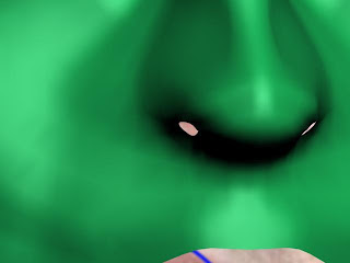
Next, I needed to view the front plane straight on, so that I could reproduce the quad-mesh in the 3D max environment. However, upon zooming into the face I found that the image displayed was very pixellated and impossible to work with. However, it was not the image that was the problem, as shown in the render to the right. I did manage to fix this problem eventually by increasing the picture quality displayed in the environment, within Max's internal options.

I then proceeded to use the line tool to trace the quads from the image. I found that some of the lines I had drawn on the original image did not line up or connect properly, sometimes having shapes with five sides that should not have been there. Therefore I improvised and added new lines where necessary. Once finished, the lines formed a flat mesh of the face. The lips and nostrils were not drawn into the mesh as they were more complex and needed to be added later in the process.
In the tutorial it is suggested that the quads be simplified and reduced in number. However, I had a great deal of trouble removing any without changing the overall shape of the face, so unfortunately the end result was quite complex.

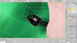
The next step was to convert this flat mesh into an editable poly. However, when I did so I found that the lines had not been drawn quite right, resulting in a hole above the nostril that was not supposed to exist.

After a few hours of trying to fix the hole, I found that I could not find a way to do it. I believe the problem was where I was adding new lines to fix the inconsistencies with the original image. However, I then re-drew the mesh within Max, drawing the quads in a more orderly fashion, adding the new quads I had discovered (in my first attempt) as I worked my way down the face, rather than adding them in afterwards. The result this time was much more pleasing, and the polygon turned out correctly. It is now ready for forming into a 3D representation of the face.


Tuesday, 7 October 2008

Week 2 - Defining Topology

The next stage was to draw the topology of the face onto the photos in Photoshop.
First, I drew on the basic shapes using blue lines on a seperate layer.


Once this was done, I could then use these lines as guidelines to make a kind of mesh of the face, built up of four sided quads. This mesh will be used to define the shape of the polygons when it is converted into 3D.


I only needed to define the topology of one half of the face. In 3D max, half of the face will be modelled, and then later mirrored to create a whole face. Lastly, I drew the basic toplogy on the side view, for reference later on.


Tuesday, 30 September 2008

Day 1 - Photography

To create a 3D model of my face for the project, I need a photo of the front and side of my face, so that I can line them up and draw the topology on the image.


However, upon trying to line the images up, I found a few problems. Firstly my head was at a different angle in the two photos, and secondly, the top of my head was cut off on the side image, making the two images nearly impossible to line up. So I retook the photos, and found two that would line up properly.


I then took these images into Photoshop, and lined them up so that the features were at the same level and scale as each other.